Heating Controls Wiring · Tado · Hive · Drayton Wiser · Kettering & Northamptonshire

Smart Thermostat Wiring Fault?

Your heating app says everything is fine. The thermostat shows the right temperature. But the boiler won’t respond — or won’t stop. Smart thermostat wiring faults often come down to a single misidentified conductor. We find it with test equipment, not guesswork.

S+Y
Plan Expertise
NAPIT
Registered
Test
Equipment
Same
Day Response
NAPIT Registered
No Guesswork — Proper Testing
Same-Day Response
Certified on Completion
Workmanship Guaranteed
Understanding the Problem

Why Smart Thermostat Wiring Is Harder Than It Looks

Smart thermostats look simple to install. The app guides you through it. The box includes a wiring guide. And yet, a significant number of them end up not working correctly — or working in some respects but not others — because UK heating system wiring is considerably more varied than the manufacturer’s generic diagram accounts for.

The wiring at your old programmer or thermostat tells you what conductors are present — but not necessarily what those conductors are connected to at the other end. A permanent live from the consumer unit, a switched live from a motorised valve, a feed from the boiler, or a demand signal to the pump can all appear on the same terminal block with similar cable colours. Identifying them correctly requires continuity testing, not just visual inspection.

Photos of the existing wiring — which is what most thermostat brand support teams request — are rarely sufficient for a definitive diagnosis. They show you where wires are currently connected; they don’t tell you what those wires actually do.

S-Plan vs Y-Plan: The Core Distinction
S-Plan — Two-zone valve system
Uses two separate motorised zone valves — one for central heating, one for hot water. Both valves have an end-switch that signals the boiler and pump when open. Smart thermostats installed on S-plan systems need to control each zone valve output independently.
Y-Plan — Mid-position valve system
Uses a single three-port motorised valve that moves between CH only, HW only, and a mid-position serving both. The common terminal wiring is different from S-plan and the smart thermostat must handle the mid-position correctly. Many wiring errors arise from treating a Y-plan system as if it were S-plan.
Combi boiler — Direct control
No hot water cylinder, no zone valves. The thermostat switches the boiler directly via a room thermostat demand signal (typically via a 2-wire or 3-wire connection depending on the boiler). Much simpler to wire — but the thermostat must be compatible with the boiler’s control interface.
What We Check

Common Smart Thermostat Wiring Faults

Incorrect terminal identificationThe most frequent cause of a smart thermostat that turns the heating on but can’t turn it off (or vice versa) is a conductor connected to the wrong terminal at the wiring centre or receiver. This often happens when the installer follows the new device’s wiring diagram without first confirming what each existing conductor does. Continuity testing from the wiring centre to each control point is the only reliable way to identify conductors correctly.
Missing permanent liveSmart thermostats and extension kits need a permanent live supply for their own electronics. Where the original programmer was self-powered via its own permanent live, and that conductor was disconnected during installation, the receiver or extension kit may have no power at all — appearing dead despite the wall thermostat showing a temperature. Finding and restoring this conductor is typically the first fix.
Wrong system type assumedInstallations where the installer has wired an S-plan extension kit into a Y-plan system — or vice versa — frequently result in heating that is always on, always off, or where one channel controls the other incorrectly. The mid-position valve common terminal wiring in a Y-plan system needs specific handling that S-plan wiring diagrams don’t include.
Boiler compatibility issuesNot all smart thermostats work with all boilers. OpenTherm modulation, BUS communication, and simple on/off switching are different control interfaces. A thermostat that attempts to modulate a boiler without OpenTherm support may behave erratically. Some boilers also have internal controls that need bridging or configuring when an external smart thermostat takes over demand. This needs checking against the specific boiler model.
Heating runs but won’t stop — or won’t startHeating that runs constantly after smart thermostat installation usually means the relay in the extension kit or receiver is stuck closed, or the switched live output terminal is permanently energised due to a wiring error. Heating that won’t start at all usually means the demand signal is not reaching the boiler — either a missing switched live or an open circuit somewhere in the control loop.
Bypassed or removed original controlsOlder systems may have had the original programmer wired in a non-standard way — sometimes as the only control point, sometimes bypassed to allow permanent heat. When a smart thermostat is installed into this, the expected terminal functions don’t exist in the expected form. Tracing the circuit from the consumer unit through the wiring centre to the boiler is the only reliable way to understand what a non-standard installation actually does.
How We Approach This

Why an Electrician, Not Just App Support

Smart thermostat brand support teams are well-resourced — but they work remotely and without test equipment. They can walk you through terminal assignments based on photos, but they cannot test what each conductor actually does. In a non-standard installation, or one where the wiring was modified at some point, photos are genuinely not enough.

We attend with a multifunction tester and continuity leads. We can establish which conductors are live, which are switched, and which are control outputs — and map the system from consumer unit through wiring centre to boiler and back. This tells us definitively what needs to change.

01
System Type Identification
We confirm whether the system is S-plan, Y-plan, combi, or something non-standard before touching any wiring. We check how many motorised valves are present and their type.
02
Conductor Tracing
At the wiring centre, we identify each conductor by continuity testing — confirming which terminal each cable originates from (zone valve, boiler, consumer unit) before any rewiring takes place.
03
Thermostat/Receiver Verification
We confirm that the smart thermostat’s receiver or extension kit has the correct power supply conductors and that its switched live outputs are connected to the correct load terminals.
04
System Function Test
With wiring verified, we test each control channel — CH demand, HW demand — by manually triggering from the thermostat and confirming the boiler and pump respond correctly.
We Also Install

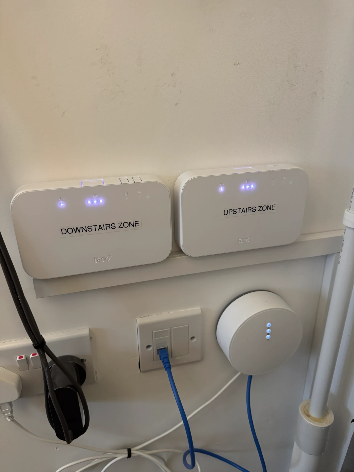
We install smart thermostats as well as diagnosing existing faults — including Tado, Hive and Drayton Wiser. We confirm your system type, wire correctly for it, and test fully before leaving. See our smart thermostat installation page for details.

Coverage

Kettering, Barton Seagrave, Corby, Wellingborough, Northampton and surrounding Northamptonshire.

Common Questions

Smart Thermostat Wiring FAQs

The most common reasons are incorrect wiring at the wiring centre or extension kit, a missing or misidentified switched live from the original controls, boiler compatibility issues, or a system wiring arrangement (S-plan or Y-plan) that the installation didn’t account for correctly. Photos of the existing wiring are helpful but rarely sufficient — the only reliable method is continuity testing to establish what each conductor actually does.
S-plan uses two separate motorised zone valves — one for central heating, one for hot water — giving independent control of each channel. Y-plan uses a single mid-position motorised valve handling both. The distinction matters significantly for smart thermostat wiring: the mid-position valve common terminal in a Y-plan system needs specific handling that S-plan wiring diagrams don’t address. Many wiring errors in smart thermostat installations result from not identifying the system type correctly before starting.
Yes. We can assess the existing installation, verify that the correct conductors are in the correct terminals at the wiring centre and receiver, confirm the system type has been correctly identified, and trace the heating control circuit from consumer unit through wiring centre to boiler to identify any errors or open circuits. We attend with test equipment, not just a wiring diagram.
It depends on the model. Battery-powered wireless thermostats (such as the Tado wireless temperature sensor) need no mains wiring — only the wired receiver or extension kit needs the full set of conductors. Wired smart thermostats and wiring centre receivers typically need a permanent live and neutral for their own power, plus switched live outputs to control the heating and hot water channels.
Fault Support

If your issue sounds similar, these pages may help you understand the fault before getting in touch.

Smart Thermostat Wiring Fault in Kettering or Northamptonshire?

We diagnose with test equipment, not guesswork — and fix smart thermostat wiring correctly regardless of system type. Cost confirmed before attendance.

Mon–Fri 8:30–16:30 · NAPIT Registered · Cost Confirmed Before Attendance